Establishing a robust and reliable Ethernet connection hinges upon the correct installation and understanding of RJ45 sockets, which serve as the cornerstone of modern networking. These connectors are not merely physical interfaces but embody a standardised system of colour coding that ensures seamless communication between devices. For technicians and installers alike, mastering the intricacies of these colour codes is paramount to achieving optimal network performance and avoiding costly errors during installation.
Decoding the rj45 colour code standards
The Role of Colour Coding in Ethernet Connectivity
The colour coding system embedded within RJ45 sockets is far from arbitrary; it represents a carefully designed standard that facilitates the identification and arrangement of wire pairs essential for data transmission. This standardised approach ensures that Ethernet cables, whether Cat5e, Cat6, or Cat6A, maintain consistent performance across diverse network installations. The colour code directly corresponds to the twisted pairs of wires within the cable, each pair serving a specific function in transmitting and receiving data. Understanding this arrangement is critical because even a minor deviation can result in signal degradation or complete failure of the connection. The standardised colour patterns allow technicians to quickly verify correct wiring without the need for extensive testing, thereby streamlining the installation process and reducing the likelihood of errors.
In practical terms, the colour code system supports both shielded and unshielded connectors, accommodating various environmental and performance requirements. Shielded connectors, for instance, provide additional protection against electromagnetic interference, which is particularly beneficial in industrial settings or areas with high electrical noise. The colour coding remains consistent across these variations, ensuring that the fundamental wiring principles apply regardless of the specific connector type employed. This universality is one of the reasons why the RJ45 standard has become so widely adopted in network installations, from residential setups to large-scale commercial deployments.
Wire pair arrangements: orange, brown, and white configurations
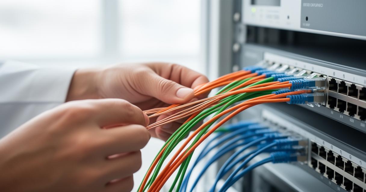
The internal structure of an Ethernet cable comprises four twisted pairs, each distinguished by a unique colour scheme that includes orange, brown, green, and blue, along with their corresponding white striped counterparts. These pairs are not randomly assigned; each serves a designated role in the transmission of data. The orange pair, for example, is typically associated with transmit functions, while the green pair handles receive operations. The brown and blue pairs can serve various purposes depending on the speed and standard of the network, with gigabit Ethernet utilising all four pairs for bidirectional communication.
The presence of white striped wires alongside their solid-coloured partners is intentional and serves to maintain the integrity of the signal. These twisted pairs reduce crosstalk and electromagnetic interference, which are common challenges in high-speed data transmission. The precise arrangement of these colours within the RJ45 socket is dictated by the wiring standard being followed, whether T568A or T568B. Each standard prescribes a specific order for these pairs, and adherence to the chosen standard across an entire network installation is crucial for ensuring compatibility and performance. Mixing standards within a single installation can lead to connectivity issues and complicate troubleshooting efforts.
T568A versus T568B: Understanding the Wiring Distinctions
Straight-through and crossover cable applications
The two predominant wiring standards, T568A and T568B, differ primarily in the order in which the wire pairs are arranged within the RJ45 connector. Despite this variation, both standards deliver identical performance in terms of data transmission speed and reliability. The choice between the two is often driven by regional preferences, organisational standards, or specific application requirements. In the United Kingdom and many other regions, T568B has become the more commonly adopted standard, though T568A is still prevalent in certain sectors and legacy installations.
A straight-through cable, which is the most common type used in network installations, employs the same wiring standard at both ends. This configuration is ideal for connecting devices such as computers to switches, routers, or wall sockets. In contrast, a crossover cable utilises T568A at one end and T568B at the other, effectively swapping the transmit and receive pairs. This arrangement was historically necessary for direct connections between similar devices, such as two computers or two switches, without the intermediary of a hub or switch. However, with the advent of Auto-MDIX technology in modern networking equipment, the need for crossover cables has diminished significantly, as devices can now automatically detect and adjust for cable type.
Understanding when to use straight-through versus crossover cables remains relevant, particularly in troubleshooting scenarios or when working with older networking hardware that lacks Auto-MDIX capability. For bulk cable installations, maintaining consistency in the chosen standard across all terminations is essential to avoid confusion and ensure seamless connectivity throughout the network infrastructure.
Choosing between shielded and unshielded connectors
The decision between shielded and unshielded connectors is another critical consideration in network installation, influenced by the specific environmental conditions and performance requirements of the deployment. Unshielded twisted pair cables, commonly referred to as UTP, are suitable for most residential and office environments where electromagnetic interference is minimal. These cables are cost-effective and easier to install, making them the preferred choice for general-purpose networking applications.
Shielded twisted pair cables, or STP, incorporate an additional layer of metallic shielding around the wire pairs or the entire cable assembly. This shielding provides enhanced protection against external interference, making STP cables ideal for environments with high levels of electrical noise, such as industrial facilities, data centres, or areas with dense concentrations of electronic equipment. The use of shielded connectors in conjunction with shielded cables ensures that the protective benefits extend throughout the entire connection, from the cable itself to the termination point. Proper grounding of the shielding is essential to maximise its effectiveness and prevent potential grounding loops that could introduce additional noise.
When selecting between these options, installers must also consider the compatibility of the connectors with keystone jacks, couplers, and other termination hardware. Ensuring that all components of the network infrastructure adhere to the same shielding standard is vital for maintaining signal integrity and achieving the desired performance levels.
Practical installation and troubleshooting techniques
Proper Socket Installation in Cabinets and Junction Boxes
Installing RJ45 sockets within cabinets and junction boxes requires meticulous attention to detail and adherence to best practices to ensure long-term reliability and ease of maintenance. The physical environment plays a significant role in the success of the installation; cabinets provide a controlled space that protects connectors from physical damage and environmental factors, while junction boxes offer convenient access points for cable termination in various locations throughout a building.
Effective cable management is paramount in these installations. Proper routing and securing of cables prevent strain on the connectors and reduce the risk of accidental disconnection or damage. Utilising cable management accessories such as cable ties, brackets, and patch panels helps maintain an organised and professional appearance, which also simplifies future troubleshooting and upgrades. When terminating cables, it is crucial to strip the outer jacket carefully, untwist the pairs only as much as necessary, and maintain the correct colour order according to the chosen wiring standard. Excessive untwisting can compromise the cable's performance by increasing susceptibility to crosstalk and interference.
The use of quality crimping tools and punchdown tools is essential for achieving secure and reliable connections. Proper crimping ensures that the connector pins make solid contact with the wire conductors, while punchdown tools facilitate accurate termination in keystone jacks and patch panels. High-quality tools not only improve the consistency of the installation but also reduce the likelihood of rework and subsequent failures.
Common wiring issues and their solutions
Even with careful attention to detail, wiring issues can arise during or after installation, often manifesting as intermittent connectivity, reduced data transfer speeds, or complete connection failures. One of the most frequent problems is incorrect wire order, which occurs when the colour code sequence does not match the chosen standard. This error can result from simple oversight or confusion between T568A and T568B. Regular verification of the wire arrangement before final crimping or termination can prevent this issue.
Another common problem is inadequate cable preparation, such as stripping too much or too little of the outer jacket, or untwisting the pairs excessively. These mistakes can lead to poor contact between the connector and the wire, or increased susceptibility to interference. Ensuring that installers are trained in proper stripping and termination techniques is essential for minimising these errors. The use of cable stripping tools designed specifically for Ethernet cables can greatly improve consistency and reduce the risk of damage to the internal conductors.
Physical damage to the cable or connectors, whether from improper handling during installation or environmental factors, is another source of connectivity issues. Regularly inspecting cables for signs of wear, kinks, or crushing, and replacing damaged sections promptly, can prevent more extensive problems. In environments where cables are subject to frequent movement or stress, employing strain relief measures and robust cable management practices is advisable.
Troubleshooting wiring issues often involves the use of cable testers, which can quickly identify problems such as open circuits, short circuits, or incorrect wire mapping. These tools are invaluable for verifying that installations meet the required standards and for diagnosing issues in existing networks. Maintaining a systematic approach to troubleshooting, starting with visual inspection and progressing to electronic testing, ensures that problems are identified and resolved efficiently.
Understanding the nuances of RJ45 socket colour codes and the distinctions between T568A and T568B standards empowers technicians to execute network installations with confidence and precision. By adhering to established standards, selecting appropriate components, and employing best practices in installation and troubleshooting, professionals can ensure that their networks deliver reliable and high-performance connectivity. The knowledge of these fundamental principles not only enhances the quality of individual installations but also contributes to the overall stability and efficiency of modern network infrastructures.